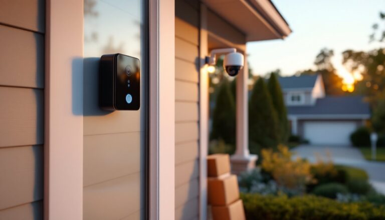
Running security camera wiring through walls, attics, or conduit often means dealing with cables that are too short or damaged mid-run. Instead of replacing the entire cable run, which can mean tearing into drywall or fishing new wire through finished spaces, splicing offers a practical fix. This guide walks through the color-coded wiring common to analog and some IP cameras, the tools needed for a solid splice, and the step-by-step process to make weatherproof, reliable connections. Whether extending a run to a remote camera location or repairing a severed cable, understanding wire color functions and proper splicing technique prevents signal loss, voltage drop, and the frustration of a camera that won’t power on.
Table of Contents
ToggleKey Takeaways
- A 4-wire color diagram for security cameras uses red (positive power), black (negative power), white or yellow (video signal), and braided shield (video ground) to ensure proper functionality and prevent damage.
- Proper splicing of security camera wires requires wire strippers, a multimeter, heat-shrink tubing, solder, and weatherproofing materials to create reliable, long-lasting connections.
- Always verify wire color and function with a multimeter before splicing to avoid reversing power polarity, which can instantly damage camera electronics.
- Heat-shrink tubing and silicone dielectric grease are essential for outdoor security camera wire splices, as electrical tape alone degrades in UV exposure and moisture.
- Testing continuity, voltage, video quality, and strain on the splice before final sealing ensures the connection will function reliably for 10+ years.
- Maintaining coaxial shield continuity is critical for rejecting electromagnetic interference and preventing signal loss that results in snowy or blank camera images.
Understanding the 4-Wire Security Camera Color Code
Most analog security cameras and many lower-voltage IP cameras use 4-wire Siamese cable, a bundled cable containing two separate runs: a coaxial video cable and a two-conductor power cable. The coaxial portion (usually RG59) carries the video signal, while the paired conductors deliver 12V DC or 24V AC power from a transformer or power supply.
Typical color codes are:
- Red wire: Positive (+) power lead, connecting to the positive terminal of the power supply
- Black wire: Negative (−) or ground power lead, returning to the negative terminal
- White or yellow wire: Video signal center conductor (inner core of the coaxial)
- Braided shield or bare wire: Video ground, surrounding the center conductor under the insulation
Some manufacturers swap white for yellow on the video center conductor, or use red/white for power instead of red/black. Always verify wire function with a multimeter or the camera’s documentation before splicing. Mixing up power polarity can damage camera electronics, while incorrect video connections result in no image.
The coaxial cable’s shield (braided copper or foil wrap) must maintain continuity for proper grounding and to reject electromagnetic interference (EMI). The power pair should be twisted or run parallel without crossing video conductors to minimize noise injection into the video signal.
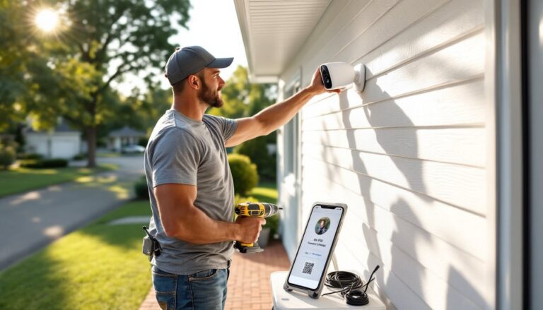
Essential Tools and Materials for Splicing Camera Wires
A clean splice requires the right tools and weatherproofing materials. Skipping any of these invites corrosion, signal degradation, or outright failure, especially outdoors.
Tools:
- Wire strippers with adjustable gauge settings (typically 18 AWG for power, RG59 for coax)
- Diagonal cutters or cable shears for clean cuts
- Coaxial cable stripper (optional but recommended for consistent RG59 prep)
- Multimeter to verify continuity and polarity after splicing
- Heat gun or lighter for heat-shrink tubing (a hair dryer works in a pinch)
- Crimping tool if using crimp connectors instead of solder
Materials:
- Heat-shrink tubing in assorted diameters (3/16″ and 1/4″ cover most wire gauges)
- Solder and soldering iron (60/40 rosin-core solder, 30–40W iron) for permanent connections
- Wire nuts or crimp butt connectors (if soldering isn’t an option)
- Electrical tape (3M Scotch Super 33+ or equivalent vinyl tape)
- Silicone dielectric grease for moisture protection on outdoor splices
- Waterproof junction box (NEMA 3R or better) if the splice will be exposed to weather
Many splices fail because the installer skipped heat-shrink or used cheap vinyl tape that degrades in UV and temperature swings. Modern smart home systems, including those reviewed by Digital Trends, emphasize reliable low-voltage connections, security cameras are no exception.
Step-by-Step Guide to Splicing Security Camera Wires
Work in a dry, well-lit area. If splicing outdoors, shield the work area from rain and dust. Wear safety glasses, solder can spatter, and wire ends are sharp.
Preparing and Stripping the Wires
- Cut the cable ends square using diagonal cutters. Ragged or angled cuts make stripping and connection harder.
- Slide heat-shrink tubing onto one cable end before stripping. You’ll need three pieces: two small-diameter pieces for the individual power wires, and one large piece (about 2″ long) to cover the entire splice.
- Strip the outer jacket back about 2″ on both cable ends. Use a utility knife carefully, score around the circumference without cutting into the inner conductors.
- Separate the coaxial and power conductors. Gently pull the coax and power pair apart.
- Strip the coaxial cable using a coax stripper or utility knife: remove about 1/2″ of outer insulation to expose the braided shield, fold the braid back, then strip 1/4″ of the dielectric (white foam) to expose the center conductor.
- Strip the power wires 1/4″–3/8″ using wire strippers set to the correct gauge (usually 18 AWG). Twist the stranded wire ends tightly to prevent fraying.
Matching and Connecting the Colored Wires
- Verify wire color and function with a multimeter. Set to continuity mode and check that red connects to the camera’s positive terminal, black to negative, and the video center conductor to the camera’s video input.
- Solder the power wires first. Match red to red, black to black. Twist the stripped ends together (a lineman’s splice or Western Union splice works well), apply flux if using it, then heat the joint and flow solder until it wicks through the strands. Let cool without moving the joint.
- Slide the small heat-shrink pieces over each power splice and shrink with a heat gun, starting at the center and moving outward to avoid trapped air bubbles.
- Connect the coaxial center conductor. Twist the center wires together and solder. Keep the joint small and tight, bulky solder joints can create impedance mismatches and signal reflections.
- Reconnect the coaxial shield. Twist the braided shields from both cables together, or wrap them and solder. This ground connection is critical for video quality.
- Cover each coax splice with small heat-shrink, keeping the center conductor and shield insulated from each other.
- Slide the large heat-shrink tube over the entire splice bundle and shrink it down. For outdoor installations, apply a bead of silicone dielectric grease inside the tube before shrinking to seal out moisture.
- Use a weatherproof junction box if the splice will be exposed. Mount the box to a solid surface (wall, fence post, soffit) and route cables through gasketed knockouts. Secure with cable clamps to prevent strain on the splice.
If soldering isn’t practical, crimp butt connectors can work for power wires, use insulated, heat-shrink butt connectors and a proper crimping tool (not pliers). For coax, twist-on or compression F-connectors paired with a barrel adapter can splice video, though this adds bulk and potential points of failure.
Common Mistakes to Avoid When Splicing Camera Wires
Reversing power polarity is the top mistake. Even a few seconds of reversed 12V DC can fry the camera’s voltage regulator. Double-check with a multimeter before applying power.
Inadequate insulation between power and video conductors invites short circuits or noise. Keep at least 1/4″ separation, and never let bare power wires touch the coax shield.
Skipping heat-shrink or using electrical tape alone leads to corrosion in humid or outdoor environments. Vinyl tape adhesive degrades in sunlight and temperature extremes. Heat-shrink provides a sealed, mechanical bond.
Using wire nuts outdoors without additional weatherproofing is asking for trouble. Wire nuts are designed for indoor, dry locations. If you must use them, encase the entire splice in a NEMA-rated junction box with a gasket.
Pulling on the splice during installation stresses the solder joints. Always leave a service loop, 12″ to 18″ of extra cable coiled near the splice, so future adjustments don’t tug on the connection.
Ignoring the coax shield or leaving it disconnected results in a snowy, rolling, or completely blank image. The shield completes the video circuit and provides EMI protection. When planning a camera installation, resources like Angi can help estimate professional labor if splicing feels beyond your skill level.
Mixing cable types (RG59 with RG6, or different power wire gauges) can work in a pinch but may introduce impedance mismatches or voltage drop. Stick with matching cable types whenever possible.
Testing Your Spliced Connection for Proper Functionality
Before sealing everything up, test every connection. This catches errors while the splice is still accessible.
- Continuity test: Set a multimeter to continuity (beep) mode. Touch probes to matching wire ends (red to red, black to black, center conductor to center conductor, shield to shield). A beep confirms a solid connection. No beep means a cold solder joint, broken strand, or poor crimp.
- Voltage test: Power on the system and measure DC voltage at the camera end. For a 12V DC camera, expect 11.5V–12.5V. Anything under 11V suggests excessive voltage drop (wire too small, splice resistance too high, or power supply undersized). For 24V AC cameras, measure around 24V AC RMS.
- Video test: Connect the camera to a monitor or DVR and check for a clear image. Look for rolling bars, static, or color shifts, signs of a poor ground or shield connection. If using a DVR or NVR system, many home security camera setups reviewed in tech guides emphasize the importance of clean coax connections for reliable recording.
- Strain test: Gently tug on the cable near the splice (don’t yank). The heat-shrink and solder should hold firm. If wires pull apart, redo the splice with better mechanical support, twist wires tighter before soldering.
- Weatherproofing check: If outdoors, spray water on the sealed splice (or wait for rain). After 24 hours, inspect for moisture inside the heat-shrink or junction box. Any water intrusion means re-sealing with more dielectric grease or a better-rated enclosure.
Document your splice locations with photos and measurements from permanent landmarks (“8 feet west of garage door, 6 feet up”). Future troubleshooting or cable additions will thank you.
A properly executed splice should last as long as the original cable, often 10+ years outdoors with quality materials. If the splice fails within weeks, revisit prep work, insulation, and environmental protection. Most failures trace back to rushed prep or inadequate sealing, not the splicing technique itself.